My GPS clock has been on duty for months and happily displaying the correct time, most of the time. It has two failings. The most important of these is that very occasionally it blacks out and displays no time at all. I have diagnosed the problem as a loss of data from the GPS. Sometimes, due to interference such as cloud, rain or low-orbiting inter-galactic spacecraft, the signal is lost and therefore the data is lost.
Version 1 was similar in features, but I used a horrible temporary mounting approach where I packed all the bits into the enclosure using shaped pieces of Neoprene. It worked as a temporary measure, but was a pain. Version 2 was built to add:

I've started work on Version 3 of the design. This revision has two goals:

Looking from the top with the removable components taken off, the GPS is at the top (brought to you by Velcro) next to the light dependent resistor (LDR), the 7-segment display is in a cut-down chip socket in the middle and the Arduino Pro Mini is in its own socket at the bottom. The only oddity here is the half chip socket for the 7-segment display is too long so, when mounted, there are two vacant pin slots at either end.

At the bottom left of the board are two leads which run to a Sparkfun USB socket break-out board. So the veroboard rail running along the edge of the board is +5V, the second rail is 0V (ground). These run the length of the board and connect to the GPS plug. More on GPS connections in a minute.
All the following notes about connections will be made looking at the component side of the board with the Arduino at the bottom.
5V Connections (positive)
As just mentioned, 5V comes in from the USB breakout board and runs down the left edge of the veroboard. Four connections come off the 5V rail:
0V from the USB breakout runs down the second rail from the left. Connections from the 0V rail go to:

Version 1 was similar in features, but I used a horrible temporary mounting approach where I packed all the bits into the enclosure using shaped pieces of Neoprene. It worked as a temporary measure, but was a pain. Version 2 was built to add:
- A circuit board
- Auto dimming of the display
- It uses an Arduino Pro Mini as the brain. It's small and limited and just perfect for a small application like this, if you can make it work!
- The serial 7-segment display and EM-406A GPS receiver share the Arduino's hardware UART and SoftwareSerial is not required (I don't like it).
- It uses the 1PPS (one pulse per second) output from the GPS to trigger updates to the display every second via an interrupt handler.
- There's no RTC making it simpler. Date/time come straight from the GPS to the display via some interpreting code that adjusts for daylight savings (Australian Eastern Time only) automatically.
- I mounted the 'expensive' components on chip sockets to make removal of parts (for reuse) easier
- The auto dimming feature works nicely
- I built my first VeroBoard circuit board
- It's powered by a USB port with no serial connection to the Arduino. Programming is done by plugging in an FTDI breakout board.
I've started work on Version 3 of the design. This revision has two goals:
- Add a real-time clock (RTC) to cover GPS "blackouts". The GPS then really only performs an initial time-set on the RTC but can be cross-referenced to check and adjust for drift.
- Change the mounting depth of the blue LED display so it isn't so blurry
I figured showing you my Version 3 work wasn't much good without fully documenting Version 2. So here goes ...
Version 2
Well, I've just tried to draw my circuit with Fritzing. Unfortunately all the parts I need were not there and when I tried to create them I ended up shaving the yak. So I'm sorry you're going to get photos with a written walk-through on the circuit instead.
Looking from the top with the removable components taken off, the GPS is at the top (brought to you by Velcro) next to the light dependent resistor (LDR), the 7-segment display is in a cut-down chip socket in the middle and the Arduino Pro Mini is in its own socket at the bottom. The only oddity here is the half chip socket for the 7-segment display is too long so, when mounted, there are two vacant pin slots at either end.

At the bottom left of the board are two leads which run to a Sparkfun USB socket break-out board. So the veroboard rail running along the edge of the board is +5V, the second rail is 0V (ground). These run the length of the board and connect to the GPS plug. More on GPS connections in a minute.
All the following notes about connections will be made looking at the component side of the board with the Arduino at the bottom.
5V Connections (positive)
As just mentioned, 5V comes in from the USB breakout board and runs down the left edge of the veroboard. Four connections come off the 5V rail:
- VCC to Arduino (bottom row, 4th pin from right)
- VCC to 7-segment display (second from left)
- 5V to LDR (second rail from right of veroboard)
- 5V to GPS (pin 2, rail 1, see EM-406A user manual)
0V from the USB breakout runs down the second rail from the left. Connections from the 0V rail go to:
- GND for Arduino (top row, 4th pin from right)
- Multiple 7-segment display pins (bare copper links)
- GND (first on left)
- SO (third from left)
- SCK (fourth from left)
- SI (sixth from left)
- CSN (seventh from left)
- 0V for LDR (rightmost rail)
- 0V to GPS (pin 1 on rail 2)
Serial Connections
As stated, the 7-segment display and GPS share the UART on the Arduino. Pin TX0 on the Arduino (top, rightmost) aligns (straight up, white link) with the receive pin on the 7-segment display (rightmost pin). This should not be a link but I cut the track by accident. Pin RX0 on the Arduino (top, second from right) connects to the third rail from the left (long diagonal white link) and goes to the GPS's RX pin (pin 3).
Reset Connection
RST on the Arduino (top, third from right) is connected to the RST connection on the 7-segment display (fourth from right) on the 7-segment display (yellow link). The display has its own microcontroller that should be reset whenever the Arduino is reset.
Interrupt Connection
Pin 2 on the Arduino (top, fifth from right) is interrupt 0 and is connected (short white diagonal link) to the fourth rail from the left and on to the one pulse per second output from the GPS, 1PPS (pin 6).
LDR Connections
Rails are from the right in this section only.
The LDR is located at the top right of the board, across rails 2 and 3. Rail 3 is connected to rail 1 via a 100kΩ resistor. As previously mentioned, rail 1 is grounded and rail 2 is at 5V. Rail 3 is connected to the Arduino's A0 analog input (bottom row, fifth from left). This is a voltage divider with the LDR attached to the 5V side, the 100kΩ resistor to ground and the middle point connected to analog input A0.
The back of the board looks like this, if you're wondering...

Setup
The key to getting the GPS and 7-segment displays to share a UART is getting them on the same baud rate. The GPS defaults to 4800 and the 7-segment display 9600. I chose to drop the 7-segment back to 4800. I uploaded this program to an Arduino, connected the 7-segment displays VCC, GND, TX and RX lines to the Arduino's 5V, GND, RX and TX respectively. When you power up you should get the 1234 display and you'll know the display's now locked to 4800 baud. This is kept in non-volatile memory, so it "sticks".
void setup()
{
  delay(5000);
  Serial.begin(9600);
  Serial.write(0x76); // reset
  delay(1000);
  Serial.write(0x76); // reset
  delay(1000);
  Serial.write(0x76); // reset
  delay(1000);
  Serial.write(0x7F);
  Serial.write(0x01); // 4800 baud
  Serial.end();
  delay(1000);
  Serial.begin(4800);
}

void loop()
{
  Serial.write(0x76); // reset
  delay(1000);
  Serial.write(1);
  Serial.write(2);
  Serial.write(3);
  Serial.write(4);
  delay(2000);
}
Don't forget you did this! If you go back to the documentation for the display or use anyone else's code (even your own) it will likely assume 9600 baud. This display won't work at 9600!
Code
The code for the GPS Clock 2 sketch is here. I won't go into the code in detail. Here are some highlights.
The code is divided into four parts:
void setup()
Here the serial port is started, remember this is being used for both the GPS and the LED display. Thus, the gps and led objects are passed a reference to the Serial port for their own use. There's some testing code and the ledPin is set up as an output to help in debugging.
Now, very important, the attachInterrupt(0, interrupt, RISING) line is what drives the display. It ensures that every second the display is updated. "Oh, I'd just use a delay(1000) statement!" I hear you say. Pah!
The delay command does not account for the execution time of the program. If your program takes 23 milliseconds to run and then you delay for 1000 milliseconds, then your program runs every 1023 milliseconds. Conversely, the 1PPS signal from the GPS will happen every 1,000,000 microseconds and the void interrupt() method will execute immediately interrupting whatever other Arduino's microcontroller is doing.
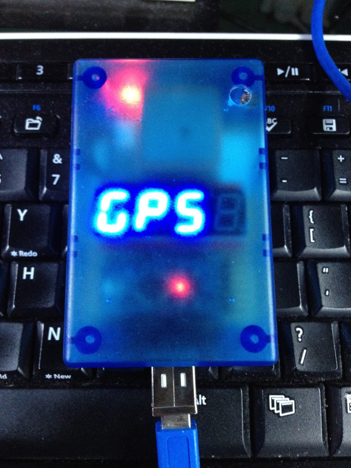
Last thing, the string "GPS " is pushed out to the LED display. It'll be frozen on the display until something else, like the correct time, comes along to replace it.
void loop()
So, while the microcontroller isn't being interrupted by the interrupt() handler, it constantly checks for new data from the GPS. That's all the loop() function does. I need to say that if the interrupt() handler takes too long, the data coming in from the GPS will overflow its tiny buffer and data will be lost. If data is lost, the NMEA sentence structure sent out by the GPS will fail validation (see GPS::isValid()) and you know what? It won't matter at all. In exactly 1 second a new data stream will come out of the GPS with the correct time in it and that will be displayed. Given the simplicity of the code it would be highly unlikely that two consecutive NMEA sentences would fail validation because of buffer overflow issues. So the clock, worst case, will be 1 second late ticking over to the next minute if a data validation failed at the turn of the minute.
void interrupt()
Gee, I've left some vestigial code lying round. Sorry 'bout that. The static boolean state variable is all about blinking the LED (on the Arduino pro, not the 7-segment display) to show data coming in.
The assumption of the interrupt() function is that the current time held in now is correct. So first, we add a second to it (which is nicely handled by the DateTime class) and then ensure it's in agreement with what just came out of the GPS. If the GPS time and the time held in now differ by more than 2000 milliseconds (see DateTime::isApproximatelyEqualTo) then an update is triggered and the gps time is transferred to the now object.
Before changing the displayed time, the brightness is checked and updated. I found interesting things happened (like MASSIVE feedback) if I only sampled the brightness once. I now use an array and average the values out over 10 samples before setting the display brightness. The result is a slow-to-respond automatic brightness control. I quite like the way it works. When I turn all the lights out it slowly dims to an appropriate value. When the lights come on it's way too dim to read but brightens relatively quickly to a very legible value. I mainly fiddled with the constant value in the line light = 1000/light; to get the brightness scaling where I wanted it.
That is all.
The code is divided into four parts:
- GPS_Clock_2, main sketch
- DateTime, a class purely for storing and manipulating date and time information
- GPS, this handles all the operations of the GPS hardware
- LED, ditto for the 7-segment display hardware
GPS_Clock_2.ino
Before setup() is called, we instantiate (create) a GPS object called gps, an LED object called led and a DateTime object called now. The now object holds the current date and time and is initialised with any old date and time.
void setup()
Here the serial port is started, remember this is being used for both the GPS and the LED display. Thus, the gps and led objects are passed a reference to the Serial port for their own use. There's some testing code and the ledPin is set up as an output to help in debugging.
Now, very important, the attachInterrupt(0, interrupt, RISING) line is what drives the display. It ensures that every second the display is updated. "Oh, I'd just use a delay(1000) statement!" I hear you say. Pah!
The delay command does not account for the execution time of the program. If your program takes 23 milliseconds to run and then you delay for 1000 milliseconds, then your program runs every 1023 milliseconds. Conversely, the 1PPS signal from the GPS will happen every 1,000,000 microseconds and the void interrupt() method will execute immediately interrupting whatever other Arduino's microcontroller is doing.
Last thing, the string "GPS " is pushed out to the LED display. It'll be frozen on the display until something else, like the correct time, comes along to replace it.
void loop()
So, while the microcontroller isn't being interrupted by the interrupt() handler, it constantly checks for new data from the GPS. That's all the loop() function does. I need to say that if the interrupt() handler takes too long, the data coming in from the GPS will overflow its tiny buffer and data will be lost. If data is lost, the NMEA sentence structure sent out by the GPS will fail validation (see GPS::isValid()) and you know what? It won't matter at all. In exactly 1 second a new data stream will come out of the GPS with the correct time in it and that will be displayed. Given the simplicity of the code it would be highly unlikely that two consecutive NMEA sentences would fail validation because of buffer overflow issues. So the clock, worst case, will be 1 second late ticking over to the next minute if a data validation failed at the turn of the minute.
void interrupt()
Gee, I've left some vestigial code lying round. Sorry 'bout that. The static boolean state variable is all about blinking the LED (on the Arduino pro, not the 7-segment display) to show data coming in.
The assumption of the interrupt() function is that the current time held in now is correct. So first, we add a second to it (which is nicely handled by the DateTime class) and then ensure it's in agreement with what just came out of the GPS. If the GPS time and the time held in now differ by more than 2000 milliseconds (see DateTime::isApproximatelyEqualTo) then an update is triggered and the gps time is transferred to the now object.
Before changing the displayed time, the brightness is checked and updated. I found interesting things happened (like MASSIVE feedback) if I only sampled the brightness once. I now use an array and average the values out over 10 samples before setting the display brightness. The result is a slow-to-respond automatic brightness control. I quite like the way it works. When I turn all the lights out it slowly dims to an appropriate value. When the lights come on it's way too dim to read but brightens relatively quickly to a very legible value. I mainly fiddled with the constant value in the line light = 1000/light; to get the brightness scaling where I wanted it.
Conclusion
And, well, that's about it. Except that I want to update the design. As I said, why blog Version 3 when Version 2 is an undocumented unknown? Version 1 was inconsequential, by the way. So, with this post out of the way, I'm going on to blog the development of Version 3, which is why I came.That is all.
Thanks for your comment. Chris.
ReplyDelete